
TL;DR:
- Proper fault detection involves inspecting physical signs like leaks and noise, along with vibration and electrical analyses to identify early component wear. Combining these methods with thermal imaging and oil analysis enhances diagnostic accuracy and prevents unplanned failures. Consistent documentation and adherence to standards like ISO 17359 improve troubleshooting efficiency and reliability.
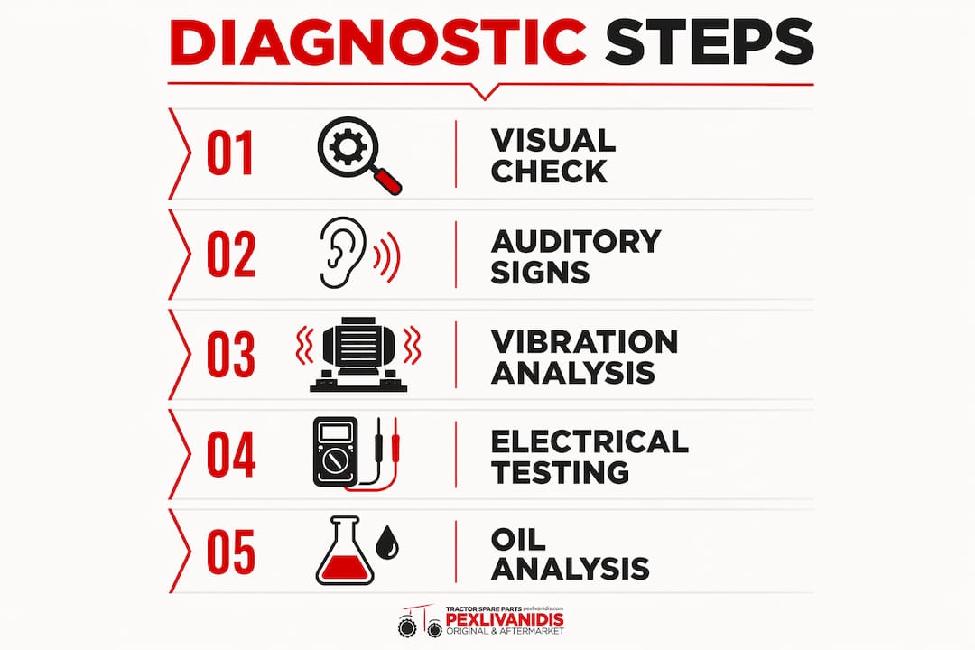
Identifying faulty machinery components is the process of detecting early signs of malfunction or wear using a combination of visual inspection, vibration analysis, and electrical diagnostics. For agricultural machinery operators and maintenance technicians, catching these faults before they escalate into full breakdowns is the difference between a planned parts swap and a costly, unplanned shutdown during harvest. The main diagnostic approaches covered here include physical symptom recognition, vibration pattern analysis, electrical system testing, and supplementary tools like infrared thermometers and oil analysis kits. Mastering these methods gives you a systematic, repeatable process for keeping tractors and field equipment running reliably.
How to identify faulty machinery components: the core signs
The first step in faulty equipment diagnosis is knowing what to look for before you reach for any instrument. Physical symptoms are the fastest and most accessible starting point for any technician in the field.
Physical damage indicators are the most visible category. Look for:
- Cracks or fractures in housings, frames, or shafts, particularly around weld joints and stress concentration points
- Corrosion on bearing surfaces, gear teeth, and hydraulic fittings, which accelerates wear and leads to premature failure
- Oil or fluid leaks around seals, gaskets, and hydraulic hose connections
- Loose fasteners on mounting brackets, PTO shafts, and gearbox covers, which allow vibration to compound damage
Auditory and operational symptoms are equally telling. A knocking sound from a gearbox almost always points to worn or broken gear teeth. A hissing noise from a hydraulic circuit indicates a pressure leak. Wobbling or rhythmic thumping from a rotating shaft suggests bearing wear or imbalance. Overheating in a component that normally runs cool signals friction from inadequate lubrication or misalignment.
Performance degradation rounds out the picture. Erratic hydraulic response, reduced lifting capacity, or inconsistent PTO speed are all signs of machine malfunction that trace back to specific component faults. A combine harvester showing uneven threshing performance, for example, often has a worn concave, a damaged rotor bearing, or a misaligned drive belt. Connecting the operational symptom to the component is the core skill in troubleshooting agricultural equipment.

Pro Tip: Keep a short checklist of auditory and visual checks for each machine in your fleet. Running through it at the start of every shift takes under five minutes and catches the majority of developing faults before they become failures.
How does vibration analysis detect faults in rotating machinery?
Vibration signals are the most common indicators for structural and rotating-part faults in agricultural machinery, helping detect wear, loosening, imbalance, and blockages even under harsh field conditions. The principle is straightforward: every rotating component produces a unique vibration signature, and deviations from that baseline reveal what is going wrong.
Vibration analysis distinguishes fault mechanisms by matching frequency patterns to known fault types. Imbalance shows as increased 1X vibration (once per revolution). Misalignment shows as elevated 1X axial and 2X radial components. Looseness produces increased 1X harmonics in the low-frequency range. Bearing wear generates high-frequency impulses at bearing defect frequencies, which are calculated from the bearing geometry and shaft speed.
| Fault type | Primary frequency signature | Typical component affected |
|---|---|---|
| Imbalance | Elevated 1X radial | Fan blades, rotors, PTO shafts |
| Misalignment | Elevated 1X axial + 2X radial | Couplings, gearbox input shafts |
| Looseness | 1X harmonics (low frequency) | Mounting bolts, bearing housings |
| Bearing wear | High-frequency impulses at defect frequency | Wheel bearings, threshing drum bearings |
To collect this data, you need a vibration sensor (accelerometer) and an analyzer. Entry-level options like the Fluke 810 or SKF Microlog provide frequency spectra that map directly to the fault table above. More advanced setups use continuous monitoring nodes mounted permanently on critical components.
Misinterpretation is a real risk in vibration diagnostics. A technician who sees elevated 1X vibration and immediately replaces a bearing may be solving the wrong problem. The actual cause could be shaft imbalance or a loose mounting bolt. Experienced technicians analyze signals along both axial and radial axes and factor in operating conditions like speed and load before drawing conclusions.
Agricultural machinery adds another layer of complexity. Harsh operating environments with dust, moisture, and variable loads complicate signal interpretation. A combine harvester running through a wet, uneven crop load will show vibration spikes that have nothing to do with component wear. Always collect baseline readings under consistent, representative operating conditions.
Pro Tip: Record vibration readings at the same shaft speed and load every time. Comparing data taken at different RPMs or under different crop loads produces false trends and leads to misdiagnosis.
Step-by-step electrical system diagnostics for agricultural tractors
Electrical faults in agricultural tractors are best isolated by starting at the power source and working outward. This approach eliminates guesswork and prevents the common mistake of replacing components that are actually functioning correctly.
Follow this sequence for systematic electrical fault tracing:
- Measure battery voltage under load. A healthy 12V tractor battery should hold above 9.6V during cranking. Use a digital multimeter set to DC voltage. A reading below 9V under load points to a failing battery or a high-resistance connection before the starter.
- Check all fuses and relays. Pull each fuse and test for continuity with the multimeter. A fuse that reads open circuit has blown, but always identify why it blew before replacing it. Test relays by swapping them with an identical relay from a non-critical circuit and observing whether the fault moves.
- Inspect wiring harnesses and connectors. Look for chafed insulation, corroded terminals, and loose connector pins. Moisture ingress into connectors is the leading cause of intermittent faults on tractors operating in wet field conditions. Clean corroded terminals with electrical contact cleaner and apply dielectric grease.
- Perform voltage-drop tests. Connect the multimeter across each section of a circuit while it is under load. A voltage drop above 0.5V across a single connection indicates excessive resistance, which generates heat and causes erratic operation. This test catches bad grounds and corroded connections that pass a simple continuity check.
- Inspect the grounding system. A tractor’s ground connection is critical. Loose or corroded grounding straps are a common cause of no-start conditions, erratic sensor readings, and misleading fault codes. Clean every ground point back to bare metal and torque the connections to spec.
- Check alternator output. With the engine running at 1,500 RPM, battery voltage should read between 13.8V and 14.4V. A reading outside this range points to a failing alternator or a voltage regulator fault. For identifying tractor electrical faults systematically, this sequence covers the majority of common failure points.
Pro Tip: Before condemning a sensor or ECU on a modern tractor, always check the ground circuit for that sensor first. A high-resistance ground can produce voltage readings that look exactly like a failed sensor.
What other diagnostic tools help assess machine components?
Beyond vibration analysis and electrical testing, three additional methods give you a fuller picture of component health without requiring disassembly.
Infrared thermometry and thermal imaging are the fastest way to spot heat-related faults. Abnormal temperature increases indicate friction, overloading, or lubrication failure. An infrared thermometer like the Fluke 62 MAX or a thermal camera like the FLIR E6 lets you scan bearings, gearbox housings, hydraulic valves, and electrical connections while the machine is running. A bearing running 20°C above its neighbors is a clear sign of inadequate lubrication or early-stage race damage.
Oil analysis goes deeper than any surface inspection. Regular oil sampling detects wear particles, contaminants, and lubricant property changes that signal internal component wear before any external symptom appears. Send samples to a laboratory like Polaris Laboratories or Castrol’s oil analysis service. The report will identify which metals are present in the oil, pointing directly to which components are wearing. Elevated iron in a gearbox sample means gear or bearing wear. Coolant contamination in engine oil means a head gasket or liner failure is developing.
CAN bus data and onboard diagnostics are underused by many technicians. Modern John Deere, CLAAS, and New Holland tractors log sensor data continuously. Pulling fault codes with a diagnostic tool like the John Deere Service Advisor or a universal CAN bus reader gives you a timestamped record of every sensor exceedance, which narrows the fault location before you touch a wrench.
Documenting symptoms, tests, and results during every diagnostic session is not optional. Consistent record keeping builds a trend database that reveals recurring problems and supports faster diagnosis on the next occurrence. A simple spreadsheet with date, machine ID, symptom, test result, and action taken is enough to start.
| Diagnostic method | Best for detecting | Equipment needed |
|---|---|---|
| Infrared thermometry | Friction, lubrication failure, overloading | Fluke 62 MAX, FLIR E6 |
| Oil analysis | Internal wear, contamination, coolant leaks | Sample kit, lab service |
| CAN bus diagnostics | Sensor faults, ECU codes, intermittent issues | Service Advisor, CAN reader |
| Vibration analysis | Imbalance, misalignment, bearing wear | Fluke 810, SKF Microlog |
Combining multiple condition monitoring techniques increases fault diagnosis reliability compared to relying on any single method. ISO 17359, the international standard for condition monitoring, formalizes this multi-method approach by requiring defined baseline measurements, alarm thresholds, and failure mode analyses before a monitoring program is considered complete.
Key takeaways
Effective machinery component diagnosis requires combining visual inspection, vibration analysis, electrical testing, and supplementary tools like oil analysis and thermal imaging into a single, documented workflow.
| Point | Details |
|---|---|
| Start with physical symptoms | Check for cracks, leaks, corrosion, and unusual sounds before using instruments. |
| Match vibration frequencies to fault types | Use 1X, 2X, and harmonic signatures to distinguish imbalance, misalignment, and looseness. |
| Trace electrical faults from the source | Start at the battery and ground system before testing sensors or replacing components. |
| Use oil analysis for internal wear | Regular sampling detects gear and bearing wear before any external symptom appears. |
| Document every diagnostic session | Trend data built over time reduces diagnostic time and prevents repeat failures. |
Why I always start with the basics before reaching for the analyzer
After years of working with agricultural machinery, the single most common diagnostic mistake I see is reaching for the vibration analyzer or the fault code reader before doing a thorough walk-around inspection. A loose mounting bolt that takes 30 seconds to find and tighten can produce a vibration spectrum that looks exactly like a failing bearing. Replacing that bearing wastes time and money, and the bolt stays loose.
The second mistake is ignoring operating context. A predictive maintenance approach treats faults as developing signatures detected early by condition monitoring. That only works if you understand what “normal” looks like for your specific machine under your specific field conditions. A combine harvester running in stony, dry soil vibrates differently than the same machine in a wet, heavy crop. Baseline readings taken in one condition cannot be compared directly to readings taken in another.
The framework I trust is the one outlined in ISO 17359, which requires you to define baselines, set alarm thresholds, and map fault signatures to failure modes before you start monitoring. It sounds formal, but even a simplified version of this process, applied consistently, produces far better results than ad-hoc checks. Build a routine inspection schedule, document everything, and treat the data as an asset. The technicians who do this catch faults weeks before failure. The ones who don’t are always reacting.
— George
Get the right parts when diagnosis points to replacement
When your diagnostic process confirms a faulty component, the next step is sourcing a quality replacement without delay. Pexlivanidis carries over 20,000 agricultural machinery parts and tractor accessories, covering bearings, hydraulic components, electrical parts, and drivetrain components for the most common tractor brands operating in Greece and the wider region. Free shipping applies to orders over 100€ within Greece, and wholesale B2B pricing is available for workshops and fleet operators. Browse the essential machinery parts guide to identify the exact component category you need, or visit peak performance maintenance for guidance on preventive replacement schedules that reduce unplanned downtime.
FAQ
What are the first signs of a faulty machinery component?
The earliest signs include unusual noises (knocking, hissing, or rhythmic thumping), visible leaks or corrosion, loose fasteners, and a drop in operational performance such as reduced hydraulic pressure or erratic PTO speed. Catching these symptoms early prevents minor wear from becoming a full component failure.
How do I check machinery parts for electrical faults?
Start by measuring battery voltage under load with a multimeter, then check fuses and relays for continuity, inspect connectors for corrosion, and perform voltage-drop tests across each circuit section. Always inspect the grounding system last, since a corroded ground point can mimic almost any electrical fault.
What does vibration analysis tell you about machinery defects?
Vibration analysis identifies fault types by their frequency signatures: imbalance appears at 1X (once per revolution), misalignment at 1X axial and 2X radial, and bearing wear at high-frequency defect frequencies. Matching the measured spectrum to these patterns pinpoints the root cause without disassembly.
When should I use oil analysis for detecting machinery issues?
Oil analysis is most useful for detecting internal wear in gearboxes, engines, and hydraulic systems before any external symptom appears. Send samples every 250 to 500 operating hours, or immediately after any suspected overload or overheating event, to catch developing faults at the earliest possible stage.
What is ISO 17359 and why does it matter for fault diagnosis?
ISO 17359 is the international standard for condition monitoring of machinery, providing a structured workflow that includes defining baselines, setting alarm thresholds, and linking observed patterns to failure modes. Following its framework makes fault diagnosis systematic and data-driven rather than reactive.